Design · Structures · Test · 2024/25 · AVDASI 2, University of Bristol
Blood-Transport UAV: Joints & Fairings
Every structural interface that holds the aircraft together, designed, analysed, printed and load-tested past ultimate. Then it failed somewhere the analysis never looked.
- Autodesk Inventor
- XFoil
- Python
- FDM (PLA)
- Wind tunnel + 6-component balance
- LabVIEW
Fuselage Division Design Team Manager · Team Project Manager · Aero Specialist · Design Specialist
- 813 N
- Survived past ultimate load
- 1.95
- Governing reserve factor
- 1,011 g
- Subassembly mass
- 0.09 N
- Measured fairing drag delta
Linear load-deflection response throughout, with no stiffness knee
Centre bar in bending at the 6g × 1.5 load case
Ten flight parts, 100 % additively manufactured
Against 0.34 N run-to-run scatter, so inconclusive and reported as such
01 Requirements
The brief
Design, build and test a UAV capable of moving blood samples rapidly between a rural short-tarmac runway and a hospital test centre. Sixty students, three competing companies and one academic year, ending in a real test campaign: a wind-tunnel entry for aerodynamic data and a structural test taken past the ultimate load case.
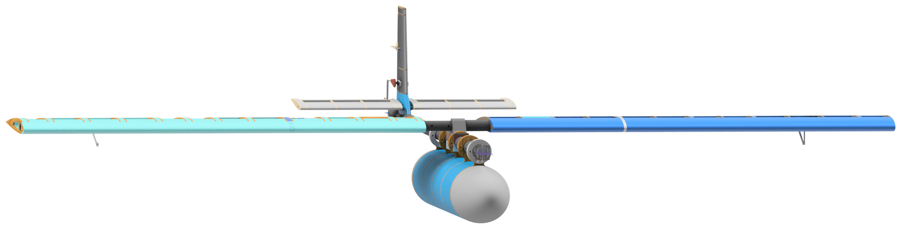
Team 08 owned the joints and fairings, meaning every structural interface that holds the aircraft together and every aerodynamic surface that covers those interfaces. That put the team downstream of six other teams and upstream of the whole airframe, because nothing assembled until these parts fit.
Requirements were tracked to a traceability matrix throughout the project, which matters more than it sounds: one of them (2.5.2.a, treating printed parts as non-structural formers) turns out to be the root of the eventual failure.
I held four roles: Fuselage Division Design Team Manager, Team Project Manager, Aero Specialist and Design Specialist. In the team's technical report I authored the project management and aerodynamics sections in full, plus the downselection and subassembly design sections.
- 01
Requirements
Mission load cases and a traceability matrix
- 02
Concept selection
Pairwise-weighted criteria feeding an MCDA matrix
- 03
Structural analysis
Reserve factors at 6g × 1.5, ahead of detailed design
- 04
Detailed design
Joints, clamps and fairings in Autodesk Inventor
- 05
Manufacture
FDM PLA, brass inserts, trial assembly
- 06
Test
Wind tunnel and ultimate load test, then failure analysis
02 Downselection
Concept selection
Criteria weighting
The rejected concepts
Fairings were new to the unit that year. There was no reference geometry and no guidance on what one is even supposed to look like on this airframe, only a requirement and a blank sketch. Making that tractable meant building the selection process explicitly rather than arguing about shapes.
03 Design
The aircraft
04 Detail design
Structural joints and the load-path asymmetry
Exploded
As a single part
Upper half, protected by metal
Lower half, bolt bears on PLA
05 Detail design
Aerodynamic fairings
The fairing design is an argument about drag budgets. The exposed items were the payload rings, the main wing joint, and roughly 100 mm of cylindrical wing spar. A circular section in two-dimensional flow produces on the order of ten times the drag of an aerofoil section of the same thickness. But a fairing adds wetted area, which adds skin friction, so it only pays for itself if it removes more form drag than the friction it introduces.
Section
Planform
Assembly, front
Assembly, rear
06 Analysis
Structural analysis before detailed design
All checks ran at 6g with the standard aerospace 1.5 factor on top, giving a design load of nine times the 1g load. They were completed ahead of detailed design on purpose, so the design team had limits to work inside rather than an audit to fail afterwards.
Centre of mass
Root torsion
| Part | Check | RF |
|---|---|---|
| Centre bar | Bending | 1.95 |
| Spar | Bearing | 2.4 |
| Flange | Prying | 3.4 |
| Spar | Tension | 4.4 |
| Spar | Shear | 5.1 |
| Pin | Shear | 7.4 |
| Spar | Cleavage | 8.9 |
| Lug | Prying | 39.0 |
Reserve factors
Mass budget
Two numbers in that table are worth more than the pass/fail verdict. The 1.95 is the design point, conservative by construction and the predicted first failure. The 39.0 is a defect: a reserve factor that high means 39 times more material than the load requires, and on a vehicle where mass drives take-off performance that is a mass saving sitting on the table. It was never claimed.
The mass record is less flattering. Of the 1,011 g total, only 269 g carries load. The other 742 g is aerodynamic shell, and against the competing companies the fairings came out 3.1 times heavier than the lightest.
The cause was a single early decision to commit entirely to FDM PLA. That bought fast iteration and the compound curves the project genuinely needed given how much the interfaces moved, and it cost mass. What makes it a real error rather than an accepted trade is that some parts never changed: the nose cone was stable from early on and could have been Styrofoam at no schedule risk.
07 Experiment
Aerodynamics: prediction against tunnel
At the tunnel speed of 20 m/s the wing sits at a Reynolds number of 4.1×10⁵ and Mach 0.058. Compressibility is irrelevant at that condition, but transition is sensitive to surface finish and freestream turbulence, which is why XFoil and the tunnel were never going to coincide.
XFoil vs tunnel
Drag vs angle of attack
The conclusion is not that XFoil was wrong. A 2D, infinite-span, smooth-surface model is a lower bound on drag and an upper bound on lift, and should be read as such. The dominant discrepancy is finite span: tip vortices generate induced drag that is entirely absent from a 2D solution.
Original drag polars: XFoil (left pair) and tunnel (right pair)
The fairing question got the more interesting answer. Averaged over the campaign, fairings-on recorded 0.09 N more drag than fairings-off, but seven repeat runs give a run-to-run standard deviation of 0.34 N. The measured difference is a quarter of one standard deviation of the noise. It is not a resolvable difference.
The test was also structurally biased against the part. The tunnel could only accommodate the fuselage, which removed the fairing's single largest justification (the 100 mm of exposed spar) from the experiment entirely, while its cost in extra wetted area was fully present.
Cutout added for tunnel clearance
Exposed spar, no wings fitted
08 Test campaign
The ultimate load test
The practice build
Load vs deflection
The airframe survived past the ultimate load case to 813 N with a linear load-deflection response throughout. The predictions that were made were sound.
Sensors were then removed to protect them, and loading continued. The recorded load went 813 N, then 804 N, then 764 N. A load drop with no visible or audible event means something has yielded, so the aircraft was disassembled and inspected.
09 Failure analysis
Then it failed somewhere else
The centre bar, reserve factor 1.95 and the predicted first failure, was undamaged. It was inspected specifically because it was expected to fail, and showed no deformation at all.
The failure was bolt shear-out through the 3D-printed PLA main-wing clamp: the wing nut pulled down into the counterbore cavity and the bolt began working through the remaining thin section of printed plastic.
Two causes, and neither is arithmetic. First, the analysis had no term for this mode: every reserve factor in the table is a check on a metallic member, because printed PLA parts were treated per requirement 2.5.2.a as non-structural formers. The analysis boundary was drawn around the parts the method knew how to handle, and never revisited when a printed part ended up in a primary load path. That is a scoping failure, and a common one in practice.
Second, the wrong clamp was fitted. Two variants existed on purpose: a wind-tunnel clamp with an 8 mm counterbore for a flanged bronze bush, and a structural-test clamp with solid material under the wing nut. The wind-tunnel clamp was fitted for the structural test because swapping it meant disassembling the pod and there was not enough time. The aircraft was loaded with a cavity directly beneath the wing nut.
10 Contribution
What I personally did
Taking four roles was a deliberate choice. The fastest way to find out which parts of engineering you are good at is to take on more than one and find out by doing.
As Design Team Manager for the fuselage division I enforced a company-wide design freeze when other teams' geometry kept moving after the design gate. It was the right mechanism applied too late, and the write-up says so. I built the divisional-level network diagrams connecting team objectives to company objectives, and worked hands-on through printing, post-processing, brass-insert fitting and trial assembly.
Work breakdown structure
Design & build phase Gantt
As Project Manager I built and kept congruent the three planning documents governing the team's year, and introduced a mandatory post-meeting reflection that measurably improved the team's self-assessed commitment scores. My critical path predicted 48 hours where the team clocked 105. The estimates were not the problem, the model was. I planned the dependencies inside my team and not the ones I did not control, which for a team sitting downstream of six others were the only ones that mattered.
Divisional network diagram
Risk rating matrix
As Aero Specialist I owned the drag-decomposition argument for the fairings, the NACA 2414 section choice, and the XFoil-versus-tunnel comparison, including the finding that the tunnel configuration could not answer the fairing question.
As Design Specialist I designed joints and fairings in Inventor and ran the concept downselection. When the company's technical director did not complete the full-aircraft CAD assembly, my design team stepped outside its remit and assembled the entire 535-file aircraft model for the company. That is the piece of the year I am most pleased with, not for the CAD, which was laborious rather than difficult, but because a small team chose to absorb someone else's failure rather than let the company miss its deadline.
The complete write-up lives in the repository: methods, data, code, provenance and limitations.
github.com/Jadbadawi/blood-transport-uav